Operating System | Ucore-Lab1
Presupposition
Some tips in assembly language
- AT&T verus Intel
1
2
OP-code dst src //Intel
OP-code src dst //AT&T - int : means making an interrupt
1
2
3
4
5
6
7
8
9
10
11
12
13
14
15
To make a system call on the x86, a program invokes the int n instruction, where
n specifies the index into the IDT. The int instruction performs the following steps:
• Fetch the n’th descriptor from the IDT, where n is the argument of int.
• Check that CPL in %cs is <= DPL, where DPL is the privilege level in the de-
scriptor.
• Save %esp and %ss in CPU-internal registers, but only if the target segment selec-
tor’s PL < CPL.
• Load %ss and %esp from a task segment descriptor.
• Push %ss.
• Push %esp.
• Push %eflags.
• Push %cs.
• Push %eip.
• Clear some bits of %eflags.
• Set %cs and %eip to the values in the descriptor. - extended inline assembly
1
2
3
4
5
asm ( assembler template
: output operands -- optional --
: input operands -- optional --
: list of clobbered registers -- optional --
);
Some usages of registers
General Registers
- AX (accumulator) : use to accumulate
- BX (base) : base register, use to index the address
- CX (count) : counter
- DX (data) : use to data transfer
Segment and pointer Reisters
- CS (code segment)
- DS (data segment)
- SS (stack segment)
- ES (extra segment)
- IP (instruction pointer)
- SP (stack pointer)
- BP (base pointer)
Some terminologies
- PIC : Programmable Interrupt Controller
Practices & Conclusion
Practice 1
Problem 1
By the code, we can see that Makefile use gcc to do the compile operation to the source code with some libs step by step and output some object(.o) files. And then it uses ld to link those .o files and produce an executable object(obj/bootblock.out). Then use sign tools to generate a standard bootblock.o. Finally, use dd to generate an ucore.img file.
- PS
- The ld command, also called the linkage editor or binder, combines object files, archives, and import files into one output object file, resolving external references. It produces an executable object file that can be run.
- dd is a command-line utility for Unix and Unix-like operating systems whose primary purpose is to convert and copy files.
- From web
1
2
3
4
5
6
7
8
9
10
11
12
13
14
15
16
17
18
19
20
GCC
-g //add gdb debug info
-Wall //to show the warnning info
-O2 //optimize processing (0,1,2,3,0 for no optimized)
-fno-builtin //only accept the builtin function start with "__"
-ggdb //let gcc generate more debug info for gdb
-m32 //build 32bits program
-gstabs //generate debug info in stabs style without gdb debug info
-nostdinc //do Not search header files in standard library, but use -l to specify
-fstack-protector-all //enable the stack and heap protection, insert protection code for all functions
-E //only do pre-handling, will not build and link
-x c //specify the C language for explicition
LDD Flags
-nostdlib //do not link the std start and standard files, just transfer the specific file to linker
-m elf\_i386 //use elf_i386 simulator
-N //set segment text and data readable and writable,cancel the page aligen in segment, cancel the link to shared library
-e func //set the start point to symbol func
-Ttext addr //redirect the start addr to addr when linking(i.e set 0 if not specify this))
Problem 2
We can get the check logic of the image from the tools/sign.c. It shows us that an image size should less than 510 bytes and end with 0x55, 0xAA.
Pratice 2 & 3
In those pratices, we used gdb to debug the bootblock. The steps are as follow.
- The BIOS loads this code from the first sector of the hard disk into memory at physical address 0x7c00 and starts executing in real mode with %cs=0 %ip=7c00, so the cpu load the 0x7c00 for the first command.
- Do something init like register eax, ds, es, ss.
- Enable the A20 mode to be compatible with the low address(20bits) for using high address(like 32bits). If we don’t get A20 mode enabled, the address higher than 1MB(1088kb) will be wrapped around to zero by default in real mode.
- Prepare the gdt and gdtdesc structure then use lgdt command to transport them to registers.
- Set CR0 register (protected mode) to 1 so that we got protected mode enabled.
After the registers under the protected mode prepared, at this time, we had finished processor preparation to execute code with 32-bits address. Next, we will set the ebp and esp registers so that can execute bootmain.c.
Pratice 4
Problem 1
Wait for the disk ready, and then use the supported method of hardware like outb (outb(…, 0x20)) to send the command to read sectors. Use insl to read a sector from the io.
Problem 2
First, we use the readseg method to load the ELFHDR from the kernel image(disk) to the virtual address @va. Then we use the the info stored in the ELFHDR to load the program content to the @va. Then the bootloader will call the entry point of kernel from the ELF Header so that the kernel code will take over the hardware.
Practice 5
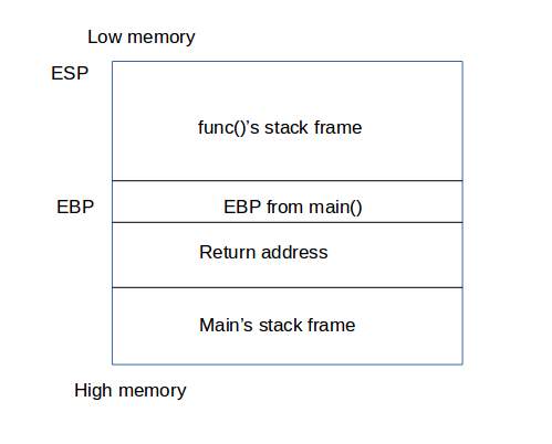
In this practice, we can use ebp and eip cleverly to trace the stackframe step by step. What we should do is getting the current ebp and eip value. With eip, we can get the debug info in current layer. Ebp’s value contains the last function ebp address before it. We can also use this ebp value to get the function params(ebp+2) and return addr (the address which should jump to when the sub function done, should taken by eip). We can trace those registers layer by layer until reach the ebp=0(means the address which the bootloader start the kernel) or the STACKFRAME_DEPTH.
- PS
- Function Stack is built from high address to low address, so that we can use ebp+1 to get the last eip register value(the address which can return to last function to resume the processing)
- Memory layout

- Function stack frame
Practice 6
Problem 1
In ucore, we can find the gatedesc at /kern/mm/mmu.h.
1 | /* Gate descriptors for interrupts and traps */ |
According to the structure, we can know that an item consist of 64bit aka 8bytes.
The low 16-32 bits saved the segment selector and we can use this to query segdesc from the GDT so that we can get the segment base address.